DIY Audio Function Generator Part 1 under Repository Circuit Diagram
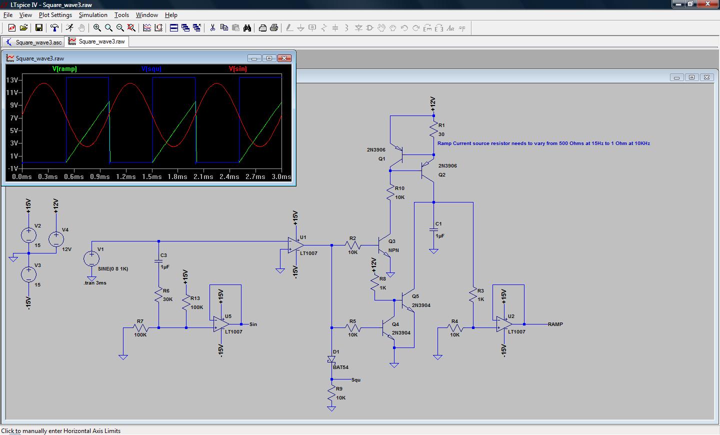
DIY Audio Function Generator Part 1 under Repository Circuit Diagram Learn how to make a square wave signal generator. With step by step instructions on how to calculate and change the frequency of the square wave. How to Build Audio Filter Circuits. Graham Lambert 3 6 min read. Learn how to build four different audio filters - high-pass, low-pass, band-pass, and notch filters. Detailed instructions and
Pulse Generator And Signal Tracer Circuit Diagram. This simple circuit generates narrow pulses at about 700-800Hz frequency. The pulses, containing harmonics up to the MHz region, can be injected into audio or radio-frequency stages of amplifiers, receivers and the like for testing purposes. A high-pitched tone can be heard from the speaker of
Audio Signal Generators and Filters Circuit Diagram
1) Using IC 4049. Using only one low-cost CMOS IC 4049 and a handful of separate modules, it is easy to create a robust function generator that will provide a range of three waveforms around and beyond the audio spectrum.. The purpose of the article was to create a basic, cost-effective, open source frequency generator that is easy to construct and used by all hobbyists and lab professionals. A tone generator circuit can be used for various applications such as alarms, bells, indicators, etc. A tone generator consists of a square, triangle, sawtooth periodic wave generator circuits, commonly square wave generators. Such periodic signals produce a beeping sound when connected to audio transducers such as a speaker, piezo, etc.
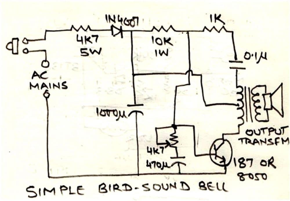
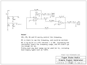
The output level of the sine wave signal is around 500mV RMS. 3) Using Audio Amplifier LM380. The circuit is built around an audio power amplifier device (IC1) utilized in a phase shift oscillator circuit. A three-section phase shift circuit is used to provide feedback between the output and the inverting (−) input of IC1. This audio frequency generator is a triggered signal generator. When a positive pulse of about 6 volts (minimum) is fed to the circuits input , a modulated audio signal comes out of the output. The signal pattern is similar to a bird's chirp. The pulse width of the trigger signal must be a minimum of 2.5 miliseconds.
Simple Tone Generator Circuit Using NE555 Timer IC Circuit Diagram
This circuit features a simple thyristor signal generator employing a single thyristor, two resistors, a capacitor and a miniature loudspeaker.. When the circuit is activated by a current source current passes through R1 activating the thyristor.. The thyristor then conducts current charging capacitor C1. As the charging current decreases inversely with the capacitors charging, it gradually - Tied a signal mode to CHANnel; so, now you may change signal form along with the frequency. - Slightly changed navigation. - Use EEPROM to store and recover settings. - Added a new signal mode: square/meander signal wave at 1/2 frequency (for even more accuracy of the output signal frequency). This is a standard feature of AD9833 module. Working Explanation. The operation of this circuit is based on the working principle of a self-triggering oscillator (astable multivibrator), performed by a 555 precision timer circuit (NE555).When the circuit is powered on, The values of resistors (R1, R2) & capacitors (C1, C2) on the left side of the circuit set the pitch of the output tone coming from the audio transducer (loudspeaker
